How are excavator front idler utilized in digging trenches for septic systems?

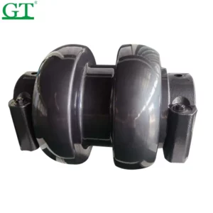
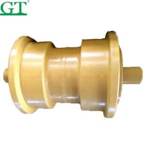
Excavator front idlers play an essential role in digging trenches for septic systems in several ways:

  1. Track Chain Support: Front idlers support and guide the excavator’s track chain, helping to distribute the machine’s weight evenly and reduce stress on undercarriage components. This ensures stability and traction, allowing the excavator to operate effectively in various soil conditions encountered during trenching for septic systems.
  2. Traction and Stability: Front idlers provide traction and stability to the excavator, allowing it to maneuver on uneven terrain and through different types of soil encountered during trenching operations. The idlers help prevent sinking or slippage, ensuring the excavator maintains its position and stability while digging trenches.
  3. Excavation Depth Control: Excavator front idlers assist in controlling the excavation depth of the trench for the septic system. By guiding the track chain, the idlers help ensure that the excavator digs to the correct depth required for the installation of the septic tank and drainage lines.
  4. Maneuverability: Front idlers enable the excavator to maneuver with precision and control while digging trenches for septic systems. excavator front idler for sale  The idlers support the track chain, allowing operators to navigate tight spaces and corners, ensuring that the trench follows the desired path and dimensions specified for the septic system.
  5. Stability During Digging: During trenching operations, front idlers help stabilize the excavator by supporting the track chain and maintaining proper tension. This stability is essential for maintaining control and accuracy while excavating trenches of varying depths and lengths for the septic system components.
  6. Excavator Performance: Front idlers contribute to the overall performance of the excavator by ensuring smooth and efficient operation during trenching for septic systems. The idlers help reduce wear and tear on undercarriage components, improve traction, and optimize the excavator’s ability to dig trenches quickly and accurately.
  7. Transportation and Mobility: Front idlers allow operators to transport the excavator to and from the job site and maneuver it into position for trenching operations. This mobility ensures that the excavator can access the site where the septic system is to be installed and efficiently complete the trenching work required for the project.

Overall, excavator front idlers are essential components for digging trenches for septic systems by providing track chain support, traction, stability, excavation depth control, maneuverability, stability during digging, excavator performance enhancement, and transportation and mobility capabilities. These features contribute to the efficiency, accuracy, and effectiveness of trenching operations for septic system installations, ensuring that the trenches are excavated to the required specifications and dimensions.

How do Track Roller contribute to landscaping tasks?

Track rollers on a mini excavator contribute to landscaping tasks in several ways:

  1. Traction and Stability: Track rollers provide traction and stability to the mini excavator, allowing it to maneuver on various types of terrain encountered in landscaping projects. This includes uneven ground, slopes, and soft or muddy soil conditions. The rollers distribute the machine’s weight evenly, minimizing ground pressure and preventing sinking or slippage.
  2. Maneuverability: The rollers allow the mini excavator to navigate tight or confined spaces commonly found in landscaping projects, such as residential yards, gardens, or urban environments. This maneuverability enables operators to access hard-to-reach areas and perform precise grading, leveling, or excavation tasks with ease.
  3. Excavation and Grading: Mini excavators equipped with track rollers are capable of digging, grading, and shaping the terrain to create features such as flower beds, garden plots, or retaining walls. The rollers provide stability and traction, allowing operators to perform precise excavation and grading operations to achieve the desired contours and elevations.
  4. Material Handling: Track rollers facilitate the movement and transport of materials commonly used in landscaping projects, such as soil, mulch, China Track Roller  gravel, or landscaping rocks. The mini excavator’s tracks provide stability and support for loading and transporting materials to different areas of the job site, streamlining the landscaping process.
  5. Attachment Compatibility: Mini excavators with track rollers are compatible with a wide range of landscaping attachments, including buckets, grading blades, rakes, augers, and hydraulic breakers. These attachments enhance the versatility of the machine, allowing operators to perform various landscaping tasks efficiently and effectively.
  6. Precision Control: Track rollers enable operators to achieve precise control over the mini excavator’s movements, allowing for accurate placement of materials and shaping of the landscape. The rollers provide stability and support for fine grading, leveling, or contouring operations, ensuring uniformity and consistency in the finished landscape.
  7. Efficiency: Using a mini excavator with track rollers significantly increases the efficiency of landscaping tasks compared to manual methods. The machine’s hydraulic-powered attachments can quickly and efficiently perform a wide range of tasks, reducing labor costs and completion time while maintaining high-quality results.

Overall, track rollers on a mini excavator are essential for landscaping tasks by providing traction, stability, maneuverability, excavation and grading capabilities, material handling support, attachment compatibility, precision control, and efficiency. These features make mini excavators equipped with track rollers versatile and effective machines for landscaping projects of various sizes and complexities.

How are excavator track roller utilized in creating garden beds or raised planters?


Excavator track rollers play several important roles in creating garden beds or raised planters:

  1. Excavation: Excavator track rollers provide traction and stability to the machine, allowing it to efficiently excavate soil to create the outline of the garden bed or raised planter. The excavator’s tracks distribute its weight evenly, minimizing ground pressure and preventing sinking or slippage during excavation.
  2. Precision Grading: Track rollers enable the excavator to perform precise grading and leveling operations within the excavated area. This ensures that the base of the garden bed or raised planter is level and uniform, providing a stable foundation for planting and landscaping.
  3. Material Handling: After excavation, track rollers facilitate the movement and transport of materials such as topsoil, compost, mulch, or landscaping rocks to fill the garden bed or raised planter. The excavator’s tracks provide stability and support for loading and transporting materials, making the process efficient and minimizing manual labor.
  4. Shaping and Contouring: Excavator track rollers enable operators to shape and contour the edges of the garden bed or raised planter to achieve the desired design and aesthetics. The machine’s precise control allows for smooth, excavator track roller manufacturers  uniform curves or angles, enhancing the visual appeal of the finished landscape.
  5. Backfilling: Once the garden bed or raised planter is filled with planting material, track rollers can be used to backfill soil or fill material around the perimeter to secure the structure in place. This helps stabilize the garden bed or raised planter and prevents shifting or settling over time.
  6. Transportation: After completing the construction of the garden bed or raised planter, track rollers allow operators to maneuver the excavator to the next location or transport it to a storage area. This capability streamlines the workflow and ensures efficient use of the equipment on the job site.

Overall, excavator track rollers are essential for creating garden beds or raised planters by providing traction, stability, precision grading, material handling support, shaping and contouring capabilities, backfilling assistance, and transportation capabilities. These features make excavators equipped with track rollers versatile and effective machines for landscaping projects, allowing operators to efficiently and accurately construct garden beds and raised planters of various sizes and designs.

What role does a sway bar ball joint play in maintaining proper suspension alignment?

A sway bar ball joint, also known as a sway bar end link or stabilizer bar link, plays a crucial role in maintaining proper suspension alignment by connecting the sway bar (also called the stabilizer bar) to the suspension components.

Here’s how it contributes to suspension alignment:

  1. Transmitting Forces: The sway bar ball joint serves as a connection point between the sway bar and the suspension control arm or strut assembly. When the vehicle encounters a bump or experiences body roll during cornering, lateral forces are transmitted from the wheels to the sway bar through the sway bar end links.
  2. Minimizing Body Roll: The primary function of the sway bar is to minimize body roll or sway during cornering. As the vehicle turns, lateral forces act on the body, causing it to lean to one side. The sway bar resists this movement by transferring force from the outer wheel to the inner wheel through the sway bar end links, helping to keep the vehicle level and stable.
  3. Balancing Suspension: By effectively distributing lateral forces between the left and right sides of the vehicle, china sway bar ball joint supplier   the sway bar helps balance the suspension and maintain proper alignment. This reduces the tendency for one wheel to lift off the ground or for the vehicle to lean excessively during cornering, improving stability and handling.
  4. Enhancing Steering Response: A properly functioning sway bar system, including the sway bar ball joints, enhances steering response by reducing body roll and improving overall vehicle control. This allows the driver to maintain better control of the vehicle, especially during aggressive maneuvers or emergency evasive actions.
  5. Preventing Uneven Tire Wear: By minimizing body roll and maintaining proper suspension alignment, the sway bar helps prevent uneven tire wear. Excessive body roll can cause the vehicle’s weight to shift unevenly onto the tires, leading to uneven tire contact patches and accelerated wear on the outer edges of the tires. Proper suspension alignment, facilitated by the sway bar system, helps ensure even tire wear and prolongs tire life.

Overall, the sway bar ball joint is essential for maintaining proper suspension alignment by transmitting lateral forces between the sway bar and the suspension components. By effectively distributing forces and minimizing body roll, the sway bar system improves stability, handling, and tire wear, contributing to a safer and more enjoyable driving experience.

How does a control arm ball joint affect vehicle dynamics and ride quality over time?

The control arm ball joint plays a crucial role in influencing vehicle dynamics and ride quality over time. Here’s how it affects these aspects:

  1. Suspension Stability: The control arm ball joint connects the control arm to the steering knuckle or spindle, allowing the suspension to move up and down while also controlling the steering angle. Over time, wear and tear on the ball joint can lead to increased play or looseness, compromising suspension stability. This can result in vague steering, wandering, and a loss of control, negatively impacting vehicle dynamics and safety.
  2. Handling and Steering Precision: A worn or damaged control arm ball joint can cause excessive play in the suspension system, affecting steering responsiveness and precision. As the ball joint wears, it may allow the control arm to move erratically, leading to unpredictable handling characteristics such as steering wheel vibration, excessive body roll during cornering, and a tendency to drift or pull to one side. This deterioration in handling can reduce driver confidence and compromise vehicle dynamics.
  3. Ride Comfort: A properly functioning control arm ball joint helps maintain consistent suspension geometry, allowing the vehicle to absorb road imperfections and shocks effectively. As the ball joint wears, it may cause the suspension to become misaligned or unbalanced, resulting in uneven tire wear, excessive vibration, china control arm ball joint  and a harsh or bumpy ride quality. This can lead to discomfort for passengers and driver fatigue, especially during long journeys.
  4. Noise and Vibration: Worn or damaged control arm ball joints can produce noise and vibration, particularly when driving over rough roads or uneven surfaces. As the ball joint wears, it may develop play or looseness, causing components to rattle or clunk during acceleration, braking, or cornering. Excessive vibration and noise can detract from the overall driving experience and indicate potential safety concerns.
  5. Alignment and Tire Wear: Control arm ball joints play a critical role in maintaining proper suspension alignment, which is essential for even tire wear and optimal handling. When a ball joint wears, it can cause the suspension to become misaligned, leading to irregular tire wear patterns such as cupping, feathering, or scalloping. Uneven tire wear not only affects ride quality but also compromises vehicle stability and safety.

Overall, the condition of the control arm ball joints significantly impacts vehicle dynamics and ride quality over time. Regular inspection and maintenance of these components are essential for ensuring optimal suspension performance, handling precision, and ride comfort. Replacing worn or damaged control arm ball joints in a timely manner can help restore vehicle dynamics, improve ride quality, and enhance overall safety on the road.

What is the typical lifespan of Fire fighting fittings?

The typical lifespan of fire fighting fittings can vary depending on several factors, including the material of construction, environmental conditions, frequency of use, and maintenance practices.

Here are some general considerations regarding the lifespan of fire fighting fittings:

  1. Material of Construction: Fire fighting fittings are commonly made from materials such as ductile iron, stainless steel, brass, or aluminum. The lifespan of fittings can be influenced by the corrosion resistance and durability of the material used. For example, stainless steel fittings tend to have a longer lifespan due to their resistance to corrosion.
  2. Environmental Conditions: The operating environment can significantly impact the lifespan of fire fighting fittings. Factors such as exposure to moisture, chemicals, temperature fluctuations, and UV radiation can accelerate corrosion, deterioration, or degradation of fittings.
  3. Frequency of Use: The frequency and intensity of use can affect the wear and tear on fire fighting fittings. Fittings that are subjected to frequent use or high-pressure conditions may experience faster deterioration compared to those used infrequently or under lower pressures.
  4. Maintenance Practices: Regular maintenance, inspections, and proper care can help extend the lifespan of fire fighting fittings. Routine inspections can identify signs of wear, corrosion, or damage early, allowing for timely repairs or replacements. Cleaning, lubrication, and corrosion protection measures can also help prolong the lifespan of fittings.
  5. Compliance with Standards: Fire fighting fittings must meet relevant industry standards and codes, such as those established by organizations like the National Fire Protection Association (NFPA) or Underwriters Laboratories (UL). Compliance with standards ensures that fittings are designed, manufactured, and installed to meet specific performance and safety requirements, which can contribute to their longevity.
  6. Manufacturer Quality: The quality of manufacturing processes and materials used by the manufacturer can also impact the lifespan of fire fighting fittings. Fittings produced by reputable manufacturers with stringent quality control measures are likely to have a longer lifespan and higher reliability.
  7. Replacement and Upgrades: Over time, fire fighting fittings may need to be replaced or upgraded to comply with changes in regulations, standards, or technological advancements. Regular assessments of the system’s performance and components can help identify opportunities for replacement or upgrades to enhance efficiency, safety, and longevity.

While it’s challenging to provide a specific lifespan for fire fighting fittings due to the variability of factors involved, proper selection, installation, maintenance, and compliance with standards can contribute to maximizing the lifespan and performance of fittings in fire protection systems. Regular inspections and proactive maintenance are essential practices to ensure the reliability and effectiveness of fire fighting fittings throughout their service life.

How do you calculate the pressure rating for Threaded welded outlet?

Calculating the pressure rating for threaded welded outlets involves considering several factors, including the material properties, dimensions, and operating conditions of the piping system.

Here’s a general method to calculate the pressure rating:

  1. Identify Material Properties: Determine the material grade and properties of the threaded welded outlet, including its tensile strength, yield strength, and allowable stress.
  2. Determine Thread Size and Type: Identify the thread size and type of the threaded welded outlet. Common thread types include NPT (National Pipe Thread) and BSP (British Standard Pipe). Ensure that the thread specifications comply with relevant standards and codes.
  3. Refer to Standards and Codes: Consult applicable industry standards and codes, such as ASME B31.1 for power piping or ASME B31.3 for process piping, to determine the pressure rating equations and factors specific to threaded connections.
  4. Calculate Design Pressure: Determine the design pressure of the piping system based on factors such as the fluid type, temperature, and operating conditions. The design pressure is typically specified by the system design engineer or dictated by regulatory requirements.
  5. Factor in Safety Margins: Apply appropriate safety factors or margins to the design pressure to ensure the reliability and safety of the piping system. Safety factors may account for uncertainties in material properties, fabrication processes, and operating conditions.
  6. Use Pressure Rating Equations: Apply the pressure rating equations specified in the relevant standards and codes to calculate the maximum allowable pressure for the threaded welded outlet. These equations typically account for factors such as thread engagement, stress concentration, and material strength.
  7. Consider Operating Conditions: Ensure that the calculated pressure rating accounts for the full range of operating conditions, including temperature variations, transient pressures, and potential system upsets.
  8. Verify Compliance: Verify that the calculated pressure rating of the threaded welded outlet meets or exceeds the design pressure and safety requirements of the piping system. If necessary, adjust the design or select a different outlet configuration to achieve the desired pressure rating.
  9. Document Calculations: Document the pressure rating calculations, including the assumptions, inputs, and results, for reference during design reviews, inspections, and maintenance activities.

It’s essential to follow established engineering practices and consult with qualified professionals when calculating pressure ratings for threaded welded outlets to ensure the safety and reliability of the piping system. Additionally, adherence to applicable standards and codes is critical to achieving compliance with regulatory requirements.

How does the surface finish of malleable iron fittings impact their resistance to corrosion?

The surface finish of malleable iron fittings plays a critical role in their resistance to corrosion. Various surface finishes can be applied to malleable iron fittings to enhance their corrosion resistance and extend their lifespan.

Here’s how the surface finish impacts corrosion resistance:

  1. Galvanized Finish: Malleable iron fittings are often coated with a layer of zinc through a process known as galvanization. This galvanized finish creates a protective barrier between the iron substrate and the surrounding environment, effectively shielding the fittings from corrosion. Zinc is highly resistant to corrosion, even in harsh environments, making galvanized malleable iron fittings suitable for applications where corrosion resistance is essential.
  2. Black Finish: Some malleable iron fittings have a black finish, which is achieved by applying a protective coating or treatment to the surface. While black-finished malleable iron fittings are not inherently corrosion-resistant like galvanized fittings, the protective coating helps inhibit the formation of rust and corrosion over time. However, black-finished fittings may still be susceptible to corrosion in certain environments, especially if the protective coating is compromised or damaged.
  3. Epoxy Coating: Malleable iron fittings can also be coated with epoxy resin to provide an additional layer of protection against corrosion. Epoxy coatings create a durable and chemical-resistant barrier that prevents moisture, chemicals, and other corrosive substances from reaching the iron substrate. Epoxy-coated  malleable iron fittings suppliers  are commonly used in aggressive environments such as chemical processing plants, wastewater treatment facilities, and marine applications.
  4. Paint Finish: Some malleable iron fittings are painted with corrosion-resistant paint to improve their durability and aesthetic appearance. The paint forms a protective layer that seals the surface of the fittings, preventing moisture and oxygen from coming into contact with the underlying iron. While paint finishes may provide limited corrosion resistance compared to other surface treatments, they offer an affordable option for protecting malleable iron fittings in less demanding applications.

Overall, the surface finish of malleable iron fittings significantly impacts their resistance to corrosion. Galvanized, epoxy-coated, and painted finishes provide effective protection against rust and corrosion, making malleable iron fittings suitable for a wide range of applications in various industries. Proper selection of surface finish based on the specific environmental conditions and performance requirements is essential for ensuring the long-term integrity and reliability of malleable iron fittings in corrosive environments. Regular inspection and maintenance of fittings are also necessary to detect any signs of corrosion and prevent potential failures in the piping system.

How does the presence of impurities or defects affect the mechanical properties of BS Standard Malleable Iron Fittings?

The presence of impurities or defects in BS standard malleable iron fittings can have significant implications for their mechanical properties and overall performance.

Here’s how impurities or defects can affect these fittings:

  1. Strength Reduction: Impurities such as sulfur, phosphorus, or silicon can weaken the structure of malleable iron fittings, reducing their tensile strength, yield strength, and ultimate strength. This compromises the fittings’ ability to withstand applied loads, pressure, or mechanical stress, increasing the risk of failure or deformation.
  2. Ductility Loss: Impurities or defects may impair the ductility of malleable iron fittings, making them more prone to cracking or fracturing under tensile or impact loads. Reduced ductility limits the fittings’ ability to deform without breaking, increasing the likelihood of catastrophic failure, particularly in dynamic or high-stress applications.
  3. Brittleness: Certain impurities or defects can increase the brittleness of malleable iron fittings, making them more susceptible to sudden fracture or catastrophic failure under mechanical or thermal stress. Brittle fittings are more prone to cracking or shattering, posing safety risks and compromising the integrity of the piping system.
  4. Corrosion Susceptibility: Impurities or defects can create localized areas of weakness or vulnerability in malleable iron fittings, making them more susceptible to corrosion or oxidation. Corrosion weakens the fittings over time, reducing their load-bearing capacity and increasing the risk of leaks or ruptures in the piping system.
  5. Dimensional Stability: Impurities or defects may affect the dimensional stability of malleable iron fittings, leading to variations in size, shape, BS Standard Malleable Iron Fittings  or surface finish. Inconsistent dimensions can compromise the fittings’ compatibility with mating components, impairing their sealing capability and integrity in the piping system.
  6. Surface Quality: Impurities or defects can manifest as surface irregularities, roughness, or discontinuities in malleable iron fittings, affecting their surface quality and integrity. Poor surface quality may interfere with the fittings’ ability to form a tight seal or bond with mating components, increasing the risk of leaks or failures.
  7. Manufacturability: Impurities or defects can pose challenges during the manufacturing process of malleable iron fittings, leading to defects such as voids, inclusions, or porosity in the finished product. These defects may compromise the fittings’ structural integrity, mechanical properties, and overall performance, necessitating quality control measures to identify and mitigate them.

Overall, the presence of impurities or defects in BS standard malleable iron fittings can have detrimental effects on their mechanical properties, reliability, and safety. Strict quality control measures, material testing, and manufacturing processes are essential for minimizing the occurrence of impurities or defects and ensuring the consistent quality and performance of malleable iron fittings in various piping applications.

How does the fabric cutting table cloth cutting machine handle fabric with varying degrees of elasticity or stretch?

Here’s how these machines typically address the challenges posed by elastic fabrics:

  1. Adjustable Cutting Parameters: Fabric cutting machines often feature adjustable cutting parameters such as cutting speed, knife pressure, and blade angle. These parameters can be optimized based on the characteristics of the specific fabric being cut, including its elasticity and stretchiness. By fine-tuning these parameters, the machine can accommodate different fabric properties and ensure clean cuts without excessive distortion.
  2. Precision Cutting Mechanisms: Fabric cutting machines utilize precision cutting mechanisms such as rotary blades, oscillating blades, or ultrasonic cutting technology. These mechanisms are designed to deliver consistent and accurate cuts through various types of fabrics, including elastic materials. By using sharp and precise cutting tools, the machine can minimize fabric distortion and produce clean edges even on stretchy fabrics.
  3. Fabric Tension Control: Some fabric cutting machines incorporate fabric tension control mechanisms to manage the stretch of elastic fabrics during cutting. These mechanisms may involve adjustable clamps, tension rollers, or vacuum systems that securely hold the fabric in place and maintain uniform tension throughout the cutting process. By controlling fabric tension, the machine can prevent excessive stretching or distortion and ensure precise cutting results.
  4. Supportive Cutting Surfaces: Cutting tables or surfaces used in fabric cutting machines are often designed to provide support and stability for elastic fabrics. These surfaces may feature non-slip materials, grid markings, fabric cutting table cloth cutting machine   or cutting guides to help align and stabilize the fabric during cutting. By providing a stable cutting surface, the machine can minimize fabric movement and distortion, resulting in more accurate cuts.
  5. Specialized Cutting Techniques: In some cases, fabric cutting machines may employ specialized cutting techniques or patterns to accommodate elastic fabrics. For example, the machine may use a zigzag cutting pattern or incorporate stretch-friendly cutting methods to mitigate the effects of fabric elasticity. These techniques help ensure that the fabric retains its shape and integrity after cutting, even if it has inherent stretchiness.
  6. Operator Expertise and Training: Proper operator training and expertise are essential for effectively handling elastic fabrics on fabric cutting machines. Operators need to understand the characteristics of different fabrics, including their stretch properties, and how to adjust cutting parameters accordingly. By applying their knowledge and skills, operators can optimize cutting performance and minimize issues such as fabric distortion or uneven cuts.

By incorporating these techniques and features, fabric cutting machines can effectively handle fabrics with varying degrees of elasticity or stretch, ensuring precise and clean cuts without compromising fabric integrity.

What Are Tee Fittings?

Fittings are commonly used to join multiple sections of tubes or pipes. They function as connectors. You can install a fitting between two pipes, for instance, to join them. While there are many different types of fittings, one of the most common is tee.

The Basics of Tee Fittings

Tee fittings are characterized by their T shape. As shown in the photo above, they feature three branches: one in the middle and two on the side. With the center branch being perpendicular to the side branches, tee fittings are shaped like the letter T. Tee fittings are commonly used in plumbing, water and fluid systems.

How Tee Fittings Work

Tee fittings are designed to join multiple sections or tubes or pipes. Most of them are threaded. There are tee fittings with external threading, such as those depicted in the photo above, and there are tee fittings with internal threading. Using this threading, you can join sections of tubes or pipes to a tee fitting.

It’s important to note that tee fittings function as branch connectors. They can take a single line and turn it into two outlets. The center branch is the main line, whereas the two branches on the side are the outlets.

Equal vs Reducing Tee Fittings

Most tee fittings fall under one of two categories: equal or reducing. Equal tee fittings feature openings of equal diameter. All three openings are essentially the same size.

Reducing tee fittings feature openings of different sizes. With reducing tee fittings, the single inlet in the center has a larger diameter than the two outlets on the side. Reducing tee fitting gs are used to divert the flow of water or fluid from a large tube or pipe to two smaller tubes or pipes.

Tee Fitting Materials

You can find tee fittings made of different materials. One of the most common materials in which they are made is aluminum. Aluminum tee fittings are lightweight, workable and highly resistant to corrosion.

In addition to aluminum, there are copper tee fittings. Copper tee fittings are more durable than aluminum tee fittings, but they also cost more. Copper tee fittings are also heavier, which may limit the applications for which they can be used.

In Conclusion

Tee fittings are vital components in many plumbing, water and fluid systems. Also known simply as tees, they are connectors shaped like the letter T.